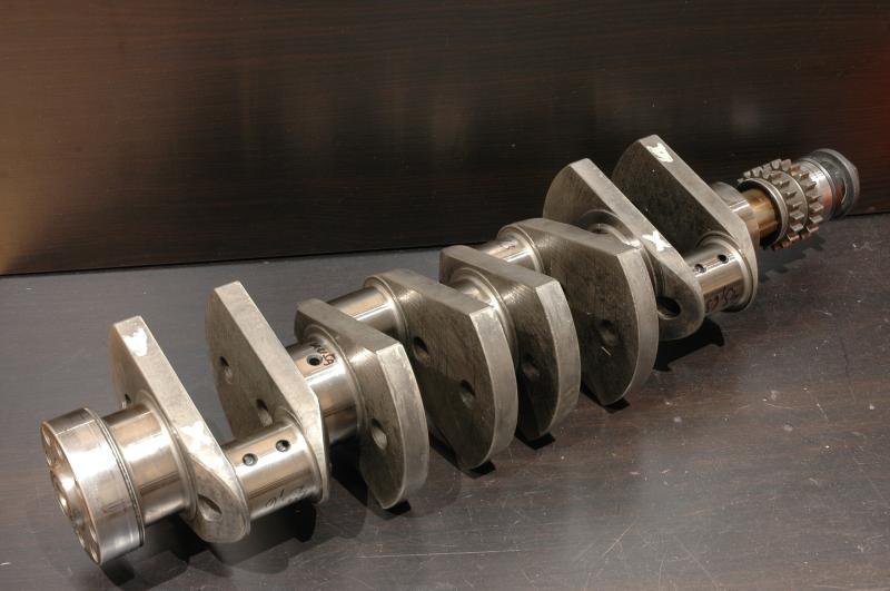
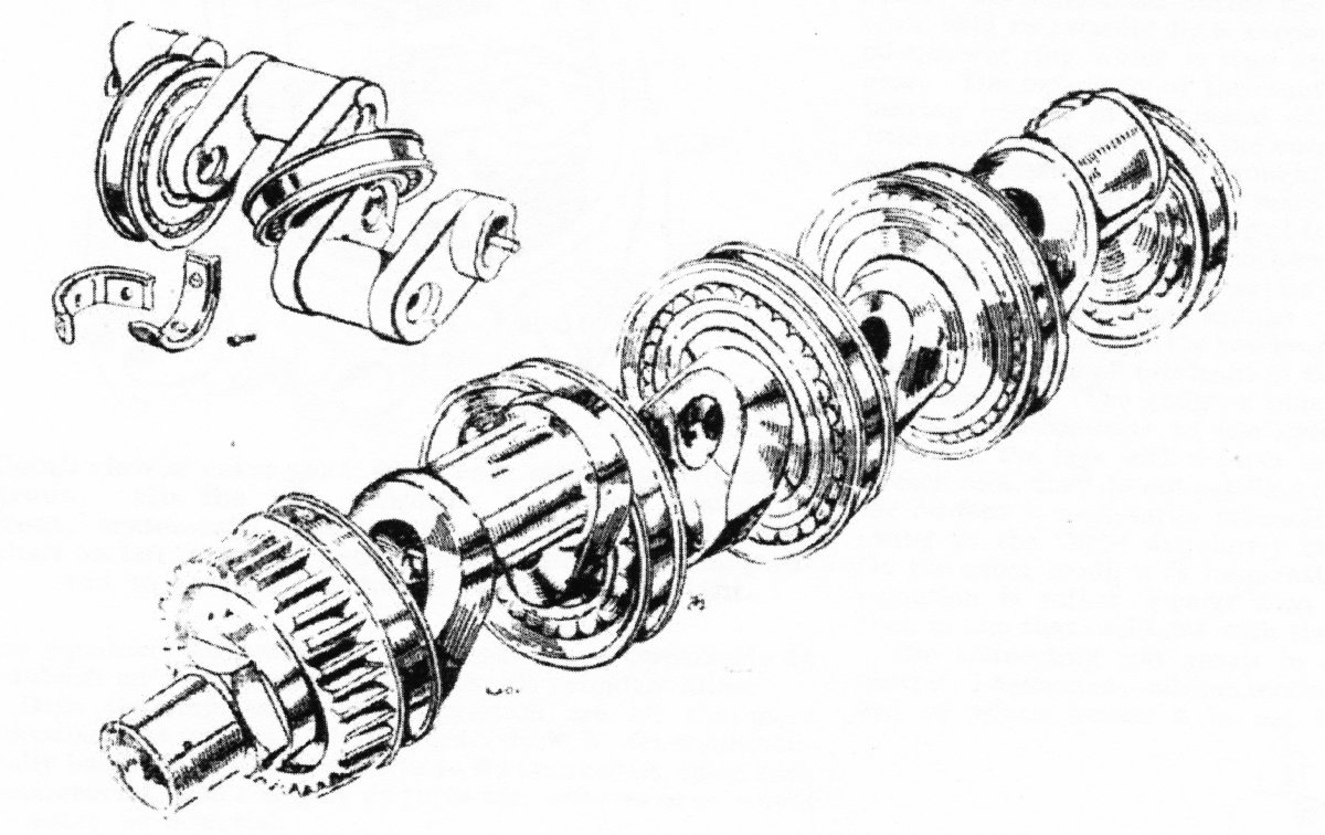
Billet Vs press-together crankshaft

Post here information about your own engineering projects, including but not limited to building your own car or designing a virtual car through CAD.
Billzilla
Billzilla
11
Joined: 24 May 2011, 01:28

Re: Billet Vs press-together crankshaft

Post

Mudflap wrote:
31 Aug 2020, 20:27
Post CAD so we can give you more confusing (and conflicting) advice!
Image

Hopefully that link will work.
The crank is far from finished there, I'm just playing with some ideas. It's a pretty conventional flat-plane crank though.
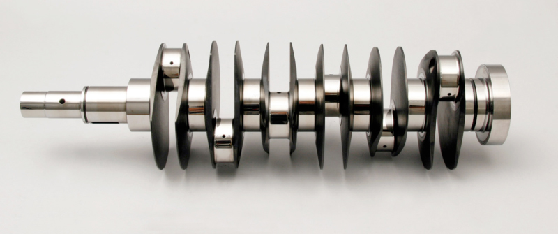
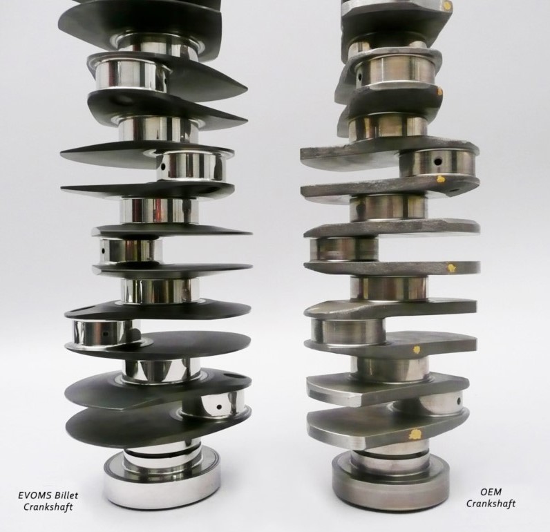
User avatar
coaster
16
Joined: 30 Jun 2012, 05:10

Re: Billet Vs press-together crankshaft

Post

A single plane with bolt on counterweights has my vote, water jet cut blank from 63.5 plate, anneal, rough machine, grind, nitride.
Water jet cuts a hefty amount machining time.

63l8qrrfy6
63l8qrrfy6
368
Joined: 17 Feb 2016, 21:36

Re: Billet Vs press-together crankshaft

Post

Billzilla wrote:
01 Sep 2020, 05:34
Mudflap wrote:
31 Aug 2020, 20:27
Post CAD so we can give you more confusing (and conflicting) advice!
https://tokyo3.org/uploads/9887a36d-166 ... 858159.jpe

Hopefully that link will work.
The crank is far from finished there, I'm just playing with some ideas. It's a pretty conventional flat-plane crank though.
Any background on this ? What engine is it going to go in? How long is it expected to last ?

The crank webs appear way too thin, particularly with so little pin overlap and tiny pin/main fillet radii. Have you checked you can achive the required MR with such skinny counterweights ?

How are you going to drill the pin thru holes in the middle 2 throws ? On a normal crank you would do blind holes at an angle to get tool access. This also allows you to have much bigger fillets on the main journal. In your design, the edge of the through hole is right next to the main journal fillet at one of the highest stress points. In bending crankshafts typically crack from the bottom of the pin fillet through to the top of the main fillet (where the edge of the hole is in your model).

Uniform web thickness is far from being efficient, you'd typically want a relatively thick diagonal section joining the pin to the main fillet and then thinning towards the counterweight. You can also drill the main journals, lots of mass to be removed there.

There isn't any clearance on the cheecks for the grinding wheel, are you planning on adding a shoulder on the cheek ?
Is there really a need to extend the web that much beyond the pin diameter? Even with a bottom guided rod the thrust area below the pin is usually sufficient.

How do you plan to make the crank ? What steel and what heat treatment ?

e36jon
e36jon
66
Joined: 25 Apr 2016, 02:22
Location: California, USA

Re: Billet Vs press-together crankshaft

Post

Not arguing with anything Mudflap had to say.

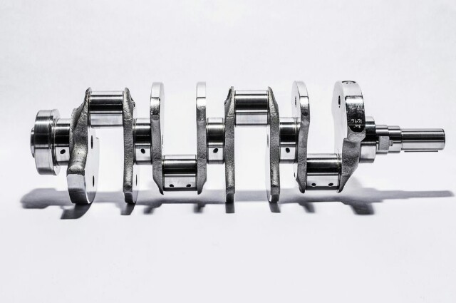
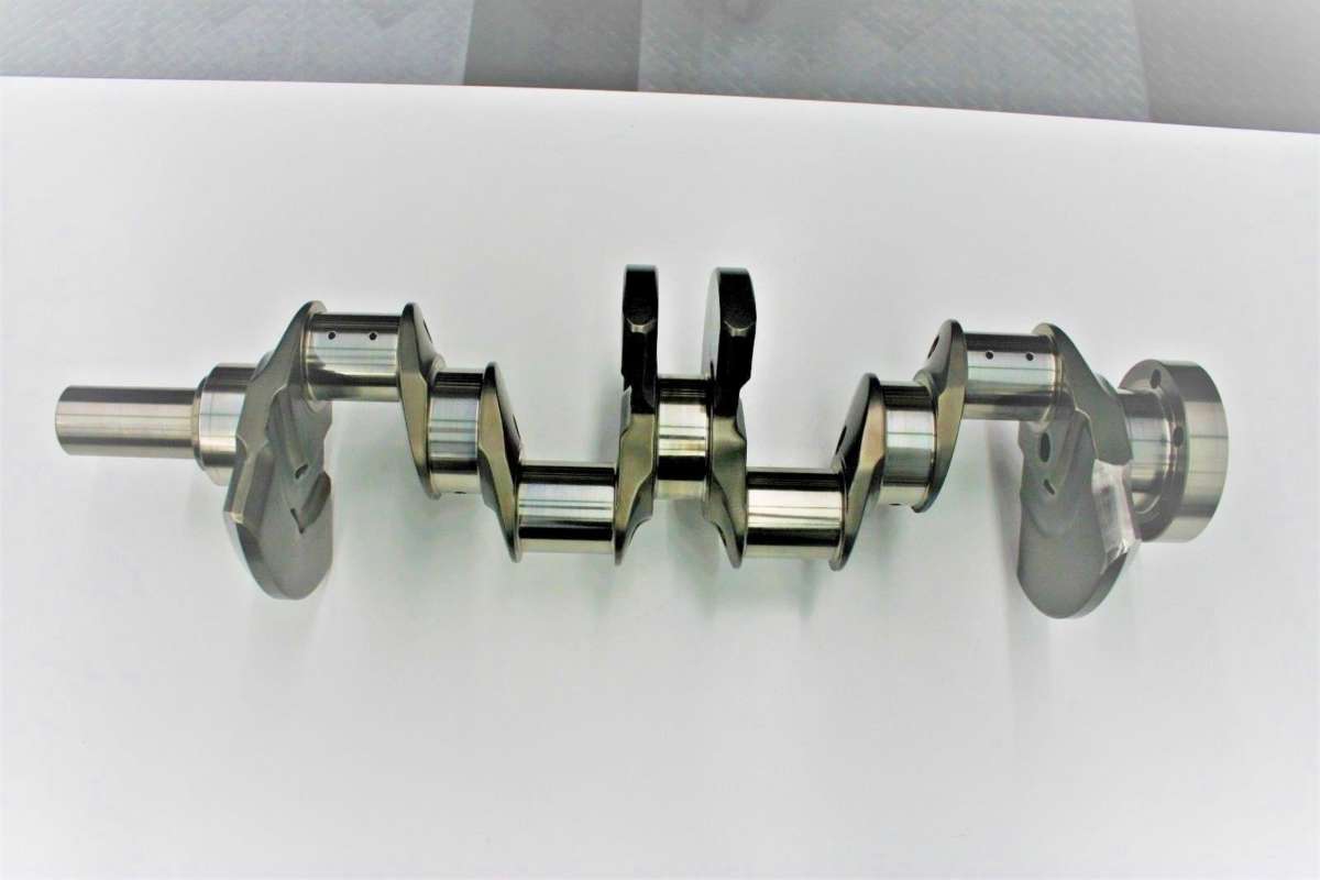
As an example of a crankshaft that always looked improbable to me, especially with regards to web-width, I give you a lightened version of the Porsche 997 GT3 from Evolution Motorsports:

Image

Image

Lots of specifics here: https://www.evoms.com/EVOMS_Lightweight ... nccrnk.htm

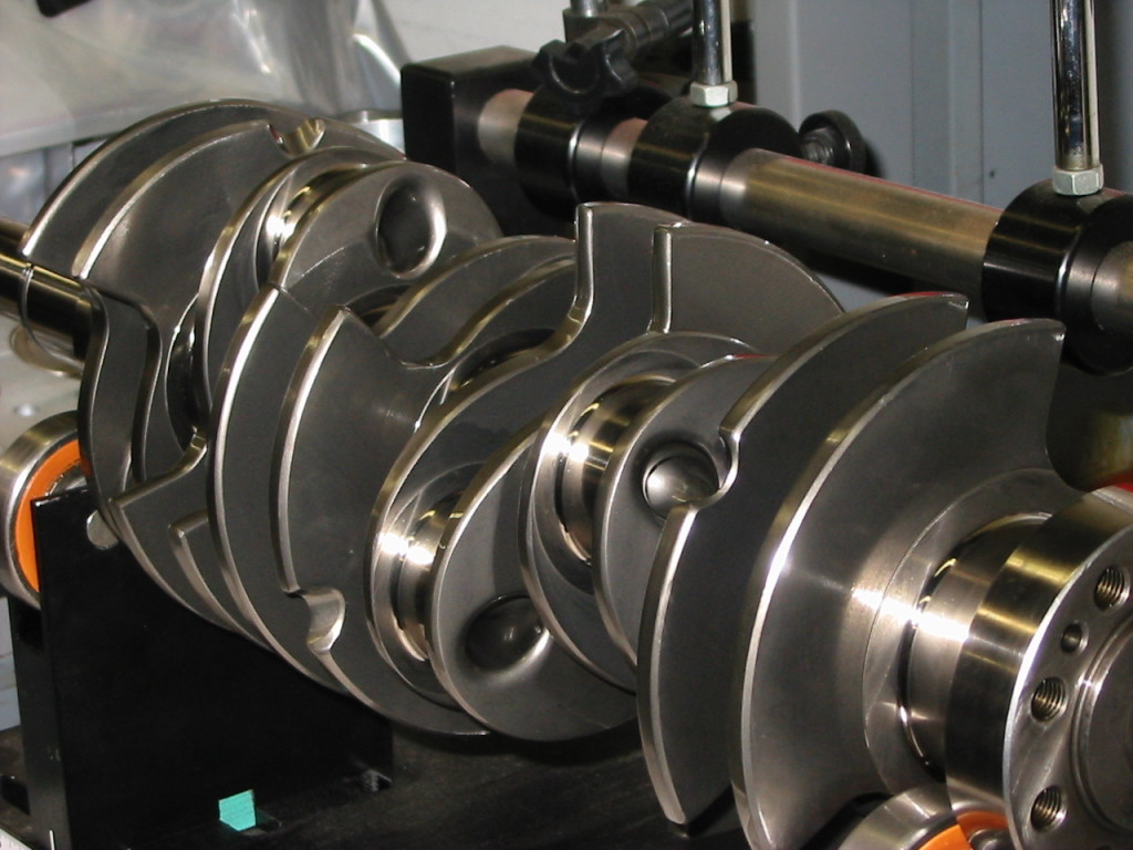
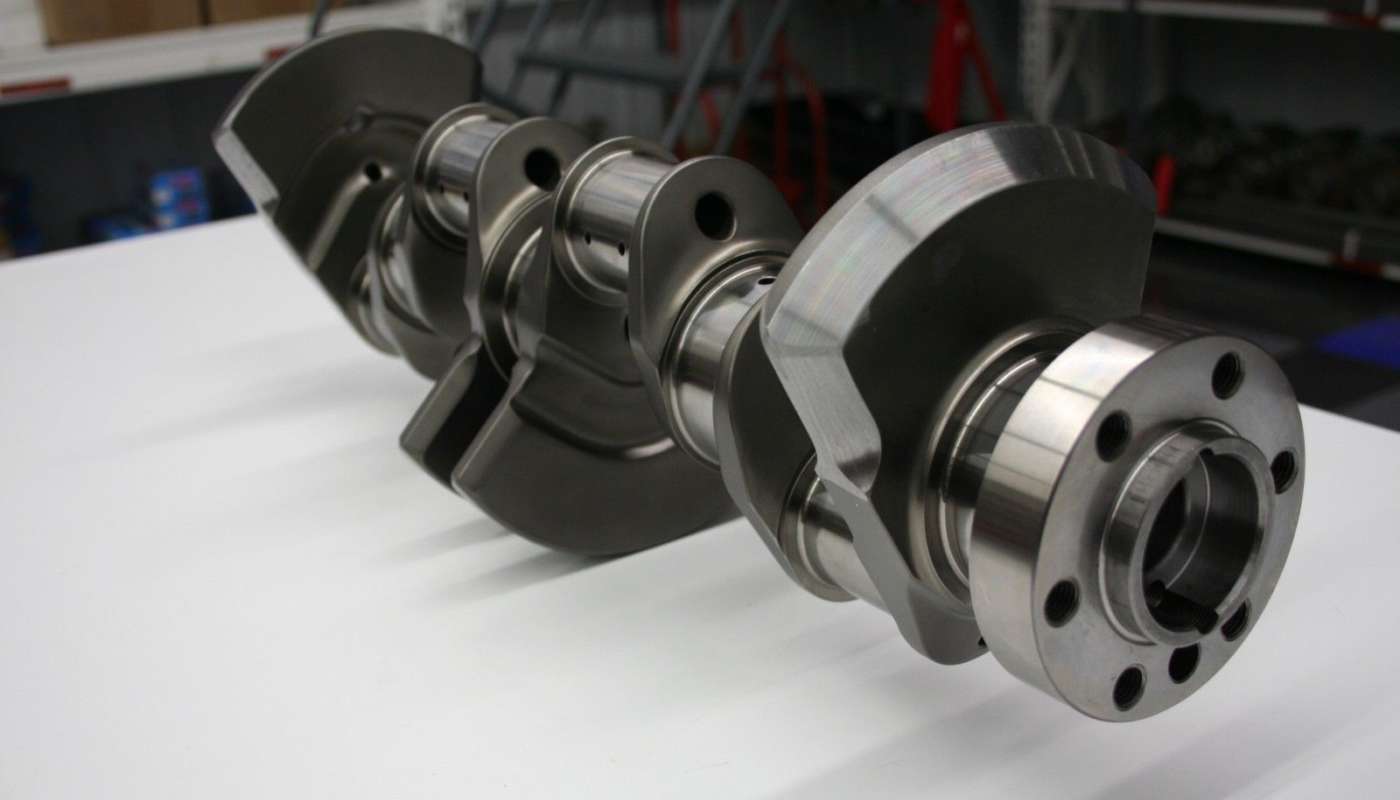
For the same vehicle here's another take from Performance Developments. Note the aggressive counterweight machining to gain better access to rod journals for lightening.

Image

Their page for this engine build is worth some time: http://performancedevelopments.com/gt3- ... placement/ At their home page they have some scary crank failure pics due to no / wrong harmonic dampers...
63l8qrrfy6
63l8qrrfy6
368
Joined: 17 Feb 2016, 21:36

Re: Billet Vs press-together crankshaft

Post

That Porsche crank has a single rod per throw so bending loads would be quite a bit lower.

Unfortunately calculating loads and stresses on crankshafts requires a bit more than just some FEA and relatively few companies have the resources to do it correctly. It's one of the reasons I am very suspicious of any highly loaded component made by small "tuning shops" which tend to have very good manufacturing facilities but very poor design offices.

IMO you should stick to a conventional crank design (any reference throw dimensions you can copy?) and refine it once you are confident everything works well.

63l8qrrfy6
63l8qrrfy6
368
Joined: 17 Feb 2016, 21:36

Re: Billet Vs press-together crankshaft

Post

e36jon wrote:
01 Sep 2020, 19:43
Their page for this engine build is worth some time: http://performancedevelopments.com/gt3- ... placement/ At their home page they have some scary crank failure pics due to no / wrong harmonic dampers...
I think this is the failure you meant?
http://performancedevelopments.com/pors ... nefailure/

They are wrong, that failure is predominantly bending fatigue. It is the classic example of crack initiating on the bottom of the pin fillet and growing through to the top of the main journal fillet that I was describing in the previous posts.
A crank loaded in pure bending (no torsion) on a rig would fail exactly like that.

The classic "harmonic" torsional fatigue failure is a crack through the middle of the crank pin, typically initiated in the oil hole fillet. The fracture face is conical and angled 45°with respect to the pin axis.

e36jon
e36jon
66
Joined: 25 Apr 2016, 02:22
Location: California, USA

Re: Billet Vs press-together crankshaft

Post

Thanks for the continuing education Mudflap...

In hopes of better supporting the conversation, here are some flat-plane V8 cranks:

Ford GT 350. Note drilling details to access pin-bosses.
Image

Custom Chevy LS
Image
Image

Ferrari V8 (F430)
Image

I'll add a few more as I find them...

Jon

63l8qrrfy6
63l8qrrfy6
368
Joined: 17 Feb 2016, 21:36

Re: Billet Vs press-together crankshaft

Post

Yea, eccentric pin bores are a simple and elegant solution. The hole edge is far from the main journal fillet, the pin drillings can go below the bore and break put on the side of the pin and it's easy to machine too. Not to mention that the mass is removed at a larger distance from the axis of rotation which means much lower inertia.

Billzilla might struggle to find an oiling drill scheme that doesn't intersect with the concentric pin bores and stays well away from the fillets as it passes through the thin webs.

Billzilla
Billzilla
11
Joined: 24 May 2011, 01:28

Re: Billet Vs press-together crankshaft

Post

Mudflap wrote:
01 Sep 2020, 17:49
Any background on this ? What engine is it going to go in? How long is it expected to last ?

The crank webs appear way too thin, particularly with so little pin overlap and tiny pin/main fillet radii. Have you checked you can achive the required MR with such skinny counterweights ?

How are you going to drill the pin thru holes in the middle 2 throws ? On a normal crank you would do blind holes at an angle to get tool access. This also allows you to have much bigger fillets on the main journal. In your design, the edge of the through hole is right next to the main journal fillet at one of the highest stress points. In bending crankshafts typically crack from the bottom of the pin fillet through to the top of the main fillet (where the edge of the hole is in your model).

Uniform web thickness is far from being efficient, you'd typically want a relatively thick diagonal section joining the pin to the main fillet and then thinning towards the counterweight. You can also drill the main journals, lots of mass to be removed there.

There isn't any clearance on the cheecks for the grinding wheel, are you planning on adding a shoulder on the cheek ?
Is there really a need to extend the web that much beyond the pin diameter? Even with a bottom guided rod the thrust area below the pin is usually sufficient.

How do you plan to make the crank ? What steel and what heat treatment ?
This ->
Billzilla wrote:
01 Sep 2020, 05:34
The crank is far from finished there, I'm just playing with some ideas.
Thanks for the extra infomation.

J.A.W.
J.A.W.
109
Joined: 01 Sep 2014, 05:10
Location: Altair IV.

Re: Billet Vs press-together crankshaft

Post

This vid shows a talented 'backyard shed' press-together crankshaft builder at work:

"Well, we knocked the bastard off!"

Ed Hilary on being 1st to top Mt Everest,
(& 1st to do a surface traverse across Antarctica,
in good Kiwi style - riding a Massey Ferguson farm
tractor - with a few extemporised mod's to hack the task).

J.A.W.
J.A.W.
109
Joined: 01 Sep 2014, 05:10
Location: Altair IV.

Re: Billet Vs press-together crankshaft

Post

This vid shows another variation, a rolling element crankshaft with split big-end conrods.

"Well, we knocked the bastard off!"

Ed Hilary on being 1st to top Mt Everest,
(& 1st to do a surface traverse across Antarctica,
in good Kiwi style - riding a Massey Ferguson farm
tractor - with a few extemporised mod's to hack the task).

Billzilla
Billzilla
11
Joined: 24 May 2011, 01:28

Re: Billet Vs press-together crankshaft

Post

Ta for that.
In the fullness of time I'll work out piston & rod masses, etc, and refine what I've drawn ....... so the experts here can demolish it. :)
I don't mind, learning is a very good thing.

J.A.W.
J.A.W.
109
Joined: 01 Sep 2014, 05:10
Location: Altair IV.

Re: Billet Vs press-together crankshaft

Post

How it was done, 'bout a century ago, viz: the 12 cylinder, 24 litre Napier Lion;
(Over-square B x S, 3 x 4 cyl banks, bevel-gear DOHC 4V) - forged, drilled, flat-crank with roller mains.

Image

& below - diagram with a bit more dry-sump, pressure-fed via crank-end - lubrication detail:

Image
"Well, we knocked the bastard off!"

Ed Hilary on being 1st to top Mt Everest,
(& 1st to do a surface traverse across Antarctica,
in good Kiwi style - riding a Massey Ferguson farm
tractor - with a few extemporised mod's to hack the task).

Greg Locock
Greg Locock
235
Joined: 30 Jun 2012, 00:48

Re: Billet Vs press-together crankshaft

Post

That Ferrari F430 one is interesting. Notice how the counterweights are symmetrical for each throw? That's an old, and not especially efficient trick, to avoid having to do FEA and stuff. Basically treat each throw as a single cylinder engine. For a production engine your aim is usually trying to minimise the maximum load in the mains, and you can normally get a solution that achieves that with less mass for a given load by considering the crank as a flexible whole. FWIW it was about 2 kg on a straight 6.

63l8qrrfy6
63l8qrrfy6
368
Joined: 17 Feb 2016, 21:36

Re: Billet Vs press-together crankshaft

Post

Greg Locock wrote:
06 Oct 2020, 22:40
That Ferrari F430 one is interesting. Notice how the counterweights are symmetrical for each throw? That's an old, and not especially efficient trick, to avoid having to do FEA and stuff. Basically treat each throw as a single cylinder engine. For a production engine your aim is usually trying to minimise the maximum load in the mains, and you can normally get a solution that achieves that with less mass for a given load by considering the crank as a flexible whole. FWIW it was about 2 kg on a straight 6.
It's funny how technology has evolved. When I started in the late 90's we used spreadsheets to calculate crankshaft bending loads as you say i.e. treating the crank as a statically determinate beam. We had simple frequency domain in-house codes to work out torsional loads and the FEA was done one HALF throw at a time.

Nowadays we just flush an entire crank through commercial multi body dynamics codes and fatigue solvers and it spits out factors of strength. It's probably twice as fast but when it goes wrong it can take days to debug.