Hopefully that link will work.
The crank is far from finished there, I'm just playing with some ideas. It's a pretty conventional flat-plane crank though.
Any background on this ? What engine is it going to go in? How long is it expected to last ?Billzilla wrote: ↑01 Sep 2020, 05:34https://tokyo3.org/uploads/9887a36d-166 ... 858159.jpe
Hopefully that link will work.
The crank is far from finished there, I'm just playing with some ideas. It's a pretty conventional flat-plane crank though.
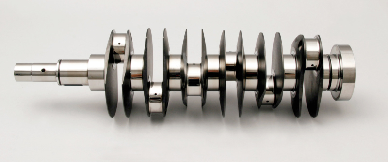
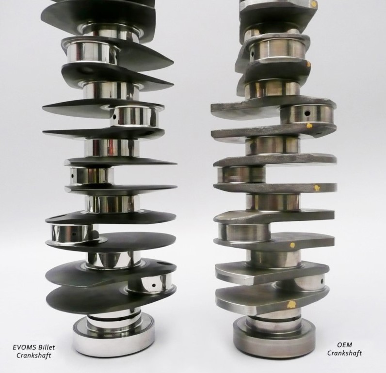
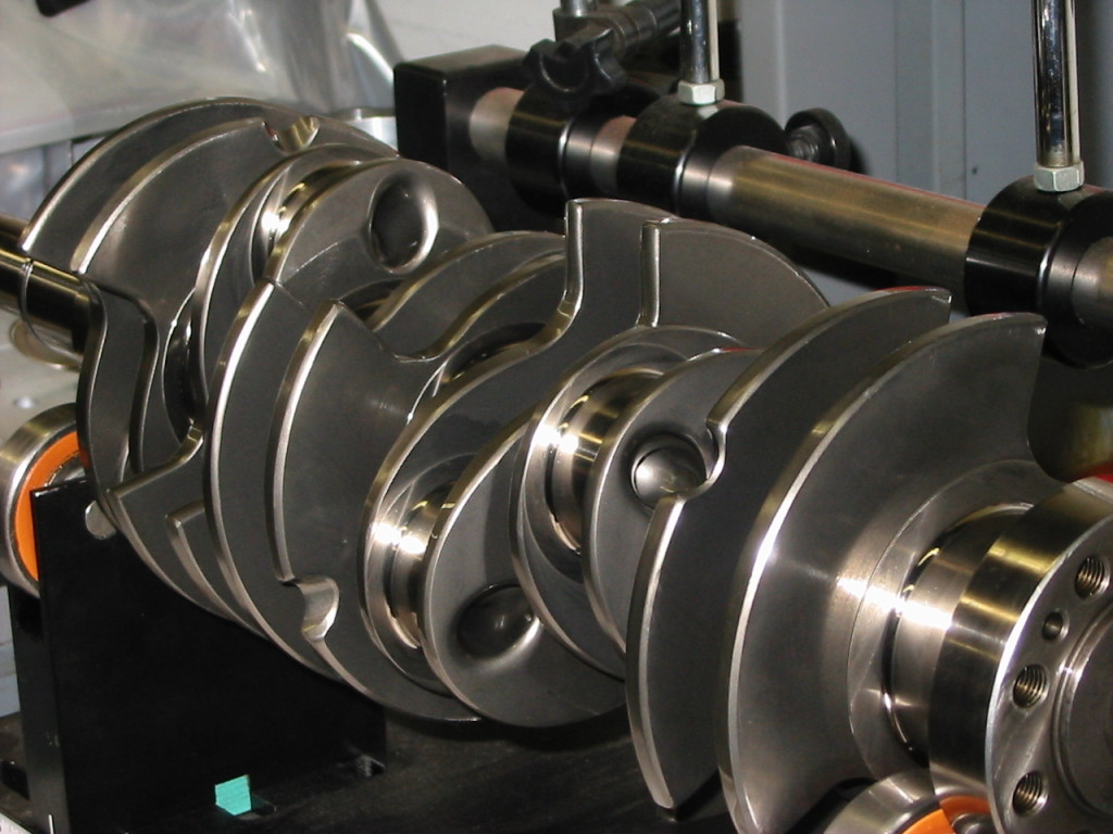
I think this is the failure you meant?e36jon wrote: ↑01 Sep 2020, 19:43Their page for this engine build is worth some time: http://performancedevelopments.com/gt3- ... placement/ At their home page they have some scary crank failure pics due to no / wrong harmonic dampers...
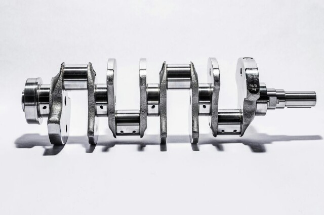
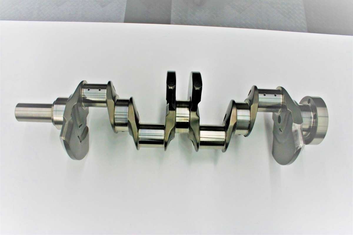
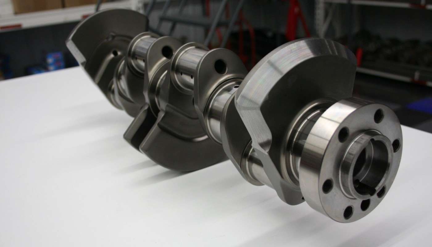
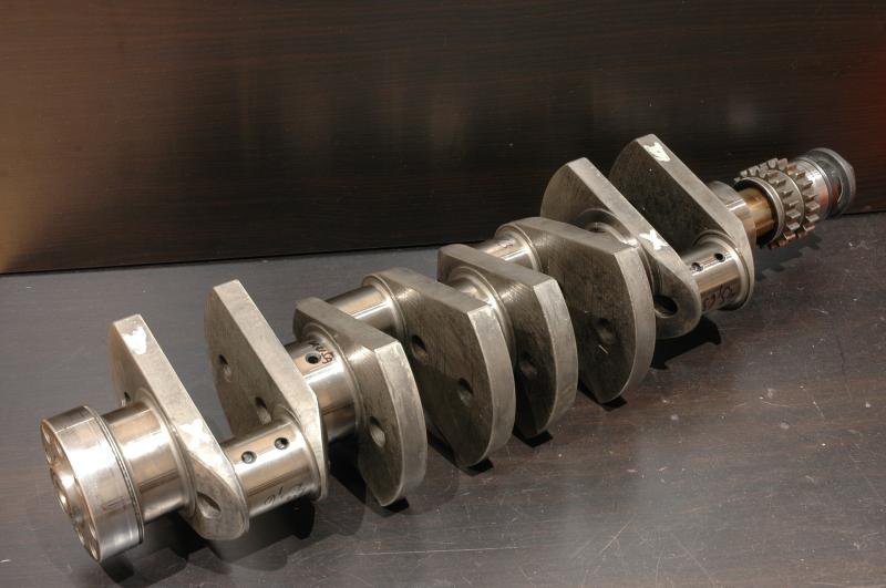
This ->Mudflap wrote: ↑01 Sep 2020, 17:49Any background on this ? What engine is it going to go in? How long is it expected to last ?
The crank webs appear way too thin, particularly with so little pin overlap and tiny pin/main fillet radii. Have you checked you can achive the required MR with such skinny counterweights ?
How are you going to drill the pin thru holes in the middle 2 throws ? On a normal crank you would do blind holes at an angle to get tool access. This also allows you to have much bigger fillets on the main journal. In your design, the edge of the through hole is right next to the main journal fillet at one of the highest stress points. In bending crankshafts typically crack from the bottom of the pin fillet through to the top of the main fillet (where the edge of the hole is in your model).
Uniform web thickness is far from being efficient, you'd typically want a relatively thick diagonal section joining the pin to the main fillet and then thinning towards the counterweight. You can also drill the main journals, lots of mass to be removed there.
There isn't any clearance on the cheecks for the grinding wheel, are you planning on adding a shoulder on the cheek ?
Is there really a need to extend the web that much beyond the pin diameter? Even with a bottom guided rod the thrust area below the pin is usually sufficient.
How do you plan to make the crank ? What steel and what heat treatment ?
Thanks for the extra infomation.
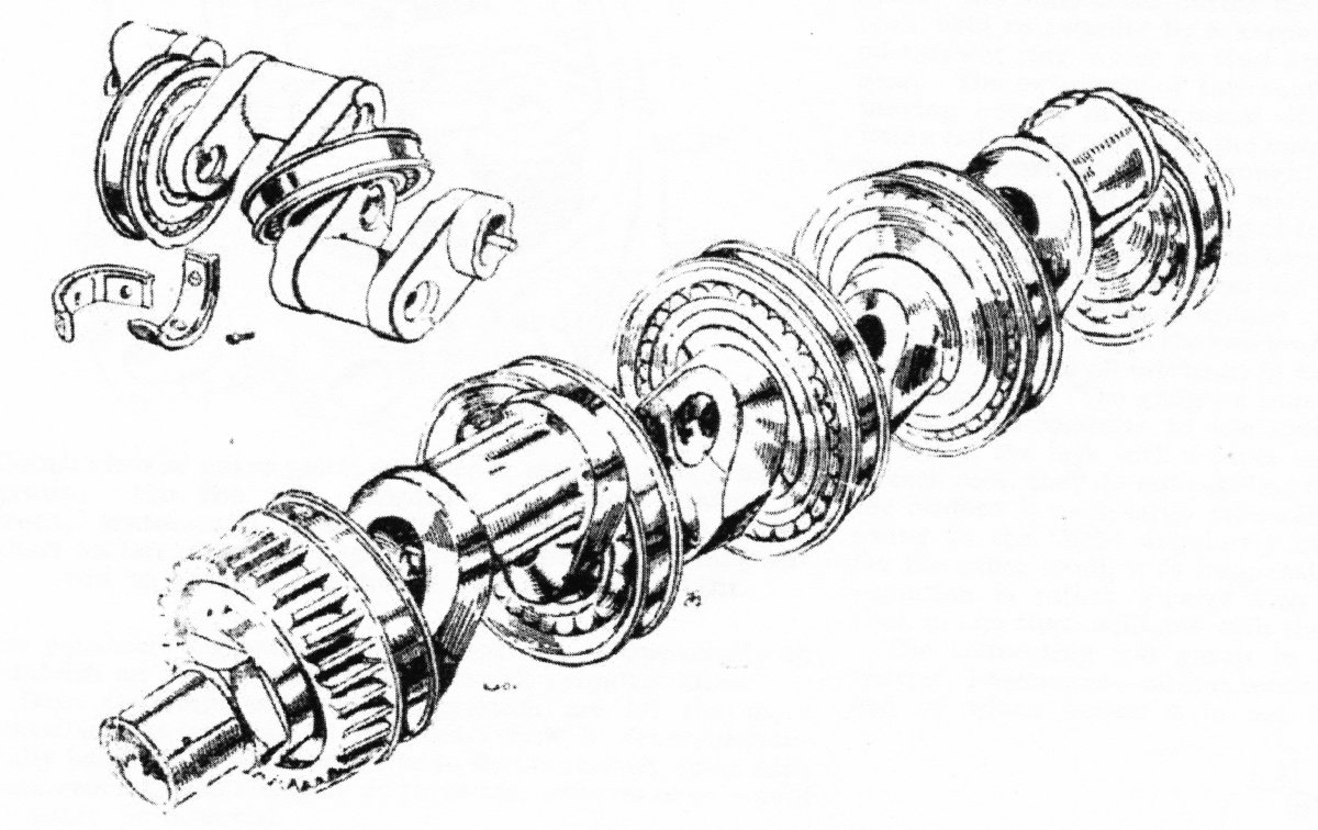

It's funny how technology has evolved. When I started in the late 90's we used spreadsheets to calculate crankshaft bending loads as you say i.e. treating the crank as a statically determinate beam. We had simple frequency domain in-house codes to work out torsional loads and the FEA was done one HALF throw at a time.Greg Locock wrote: ↑06 Oct 2020, 22:40That Ferrari F430 one is interesting. Notice how the counterweights are symmetrical for each throw? That's an old, and not especially efficient trick, to avoid having to do FEA and stuff. Basically treat each throw as a single cylinder engine. For a production engine your aim is usually trying to minimise the maximum load in the mains, and you can normally get a solution that achieves that with less mass for a given load by considering the crank as a flexible whole. FWIW it was about 2 kg on a straight 6.